FREE WEBINAR | November 24: Join us for an introduction to CNC Machining.
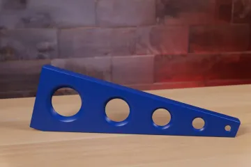
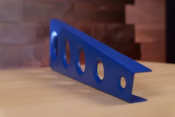
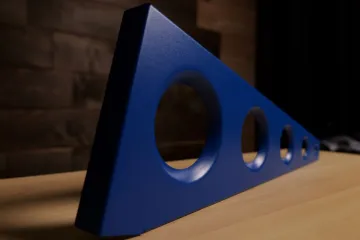
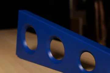
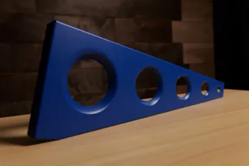
Register Now!Dimple Forming involves pressing the edge of the hole between dimple dies to form a beveled/flared edge.
It is part of our in-house services, and can be completed within our fast 2-3 day lead time.
Dimples can stiffen thin parts, allowing for increased strength while reducing overall weight.
Material can be strategically removed by adding dimples, all while maintaining the part's strength.
Small, protruding dimples create an effective anti-slip surface.
Dimples can be used for aesthetic purposes.
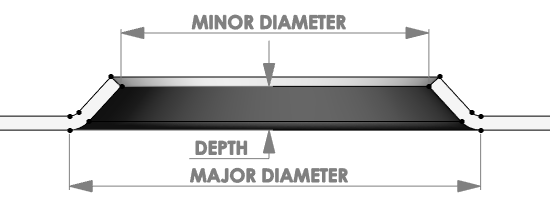
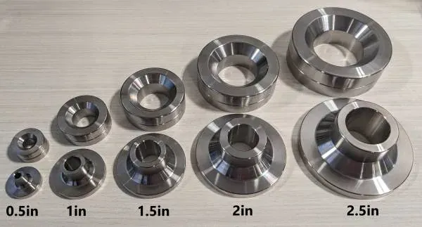
| Dimple Die Size | Minor Diameter | Major Diameter | Depth |
|---|---|---|---|
| 0.5" Dimple Die | 0.510" | 12.954mm | 0.860" | 21.844mm | 0.091" | 2.311mm |
| 1" Dimple Die | 1.037" | 26.340mm | 1.518" | 38.557mm | 0.146" | 3.708mm |
| 1.5" Dimple Die | 1.618" | 41.097mm | 2.250" | 57.15mm | 0.237" | 6.020mm |
| 2" Dimple Die | 2.186" | 55.524mm | 2.950" | 74.93mm | 0.315" | 8.001mm |
| 2.5" Dimple Die | 2.747" | 69.774mm | 3.670" | 93.218mm | 0.390" | 9.906mm |
Our stock dies are rated to handle:
Parts with no finish may show minor tool marks, cosmetic bare metal finishes will be touched up where possible.
We only guarantee tolerances on a few key dimensions:
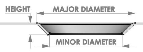
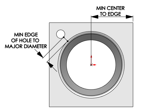
Maximum Center-To-Closest-Edge: 24" | 609.6mm
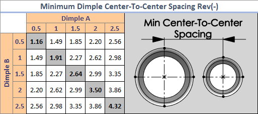
| Dimple B \ Dimple A | 0.5" | 1" | 1.5" | 2" | 2.5" |
|---|---|---|---|---|---|
| 0.5" | 1.16 | 1.49 | 1.85 | 2.20 | 2.56 |
| 1" | 1.49 | 1.91 | 2.27 | 2.62 | 2.98 |
| 1.5" | 1.85 | 2.27 | 2.64 | 2.99 | 3.35 |
| 2" | 2.20 | 2.62 | 2.99 | 3.50 | 3.86 |
| 2.5" | 2.56 | 2.98 | 3.35 | 3.86 | 4.32 |
